Please note that I just added this to my website in December 2026. Changes will be made and many additions will be added as I am currently working on this model So please periodically check back for my progress. Thank you!
Sometime in 2025 we were running RC boats at Deer Head Lake in Forked River New Jersey. One of the guys, Gary, let me take a try at his 3-4 foot sailboat. I never tried a sailboat before. I typically build and run surface runners or submarines. Well, I enjoyed running his sailboat. So I hopped on a forum and asked about different kind of kits or RTR’s that may be available. I rather enjoy building model boats from scratch although the 2-3 submarines I have are display kits that are large enough to build into radio control models. I love the 12 meter style boats and I was pointed to this kit that someone was offering online. So I bought one. It was a kit of the 12 meter 1958 America’s Cup winner Columbia. I did scratch build a sailboat when I was teenager sometime in the 70’s. It was about 24 inches long and my mom sewed up the sails. It was my first attempt at scratch building. I no longer have that boat. So here we are in soon to be 2026 and I have this kit. The nice thing about this hull is the streamline of the hull underwater. It was touted as being able to run through weeds due to the hull shape. And the lakes around here tend to be weed infested later in the summer.
My building technique can be rather slow as I am tedious and particular about how the model appears and how it works. I have been known to spend days on a particular item then scrap it due to it not being to my standards or not working to my liking. That will be seen early on in this build. I tried asking on a forum and a Facebook page for help and advice but there was not many helpful replies so I gave up on that. Therefore I just browsed around online and found what I could to help guide me on this build. And due to my skills and ingenuity I think this model will come out just beautiful and work just fine. I did get some pictures from the group of guys in Florida who seem to be a test group for this class of sailboat or yacht.
October 2026. The kit was purchased from www.columbia42.com around December 2024. The kit included the following metallic hardware (pictured). Masts and booms, hatch hardware, spreaders, mast head, jib and shroud racks, mast mounts, rudder steering arm and a few other items. Wood parts are the main deck, wood to mount the deck to the styrene hull and mounts for servos (not pictured). I received two mast and boom sets for two different sail rigs. But I only received spreaders for one mast. The smaller spreader has a larger diameter hole than the other two and larger than the mast, and I do not know why that is. I will not be using the supplied hatch hardware and the jib and shroud racks. I’ll be making my own hatches and the shroud racks will be replaced by other racks that I’ll be purchasing online, details will be provided later. For the spreaders, I already bought aluminum sheet and will be making a copy of the smaller spreader with the correct size hole and another set of spreaders for the second mast. The two sets of sails are on order from Brian at EHSails.
The Stand
October 2026. I neglected to take pictures of the wood pieces that comprise the stand prior to being painted. I started with using plywood which was 7/16″ thick. It was shaped sanded and drilled. You can see parts of the main stand section in the first picture. Dowels were used as cross members to hold the plywood sections together. The ends of the dowels were cut down in diameter on the band saw due to not fitting in my mini lathe. A back stop was setup, they were cut radially by spinning them, then they were moved side to side to to clean up the cuts. Finally they were filed and sanded down to the correct diameter to fit into the holes in the side sections. The ends were shaped and holes were drilled in the ends for pins. Everything was sanded and the dowels were glued in place. Guides were added at the top which will hold the handle string away from the boat. 1/8″ rope from West Marine was cut to length and the ends were bound into loops using the lathe as a way to hold the rope so I could move my hands around the ends binding them together. The ropes slip into the guides, the slip over the end of the dowel. So they do not slip off the dowel, pins are inserted into one of the holes to hold it in place. The ropes can be removed if I need to. I do not have support under the keel. If that is needed it would be easy enough to add. I can now carry the boat without the mast.
Rudder Foundation Pour
November 2026. A long drill bit was purchased from Amazon (about $11) in order to drill the rudder stuffing tube hole. See the captions in the pictures for the process. A section of brass was soldered to the stuffing tube to anchor the tube in the epoxy. The supplied plywood dam for this step did not fit well so a new dam was fashioned from scrap wood. Supposedly epoxy is not supposed to stick to wax paper so wax paper was glued onto one side of the plywood, hopefully for easy removal. Once the plywood was clamped into place, any gaps that could be seen were filled with Play-Doh. I’ve used Play-Doh before for figuring out what an enclosed area that cannot be viewed might look like in order to shape something for that area. The epoxy was mixed with Microballoons and some white pigment was added in a small cup then poured behind the dam and allowed to set overnight. An infrared gun was used to check the temperature as a volume of epoxy enclosed can generate a lot of heat. If it was spread on fiberglass cloth it would not generate so much heat. Fortunately, the dam did not leak and the temperature did not get that high in the pour. The next day the dam was removed. The wax paper did stick to the epoxy which was peeled of and sandpaper was used to remove the rest that stuck. Further pictures of this area will be seen in the next few steps.
Taping drill guide in place
Long drill bit from Amazon
Stuffing tube hole drilled
Trial fit of stuffing tube
Trial fit of stuffing tube
Soldered scrap brass to stuffing tube
Rudder foundation dam in place
Rudder foundation dam in place
Epoxy resin wit micro balloons and white pigment
Epoxy poured
Oops, mixed too much, this is extra
And then the extra surprisingly expanded
Temperature in the pudding cup
Temperature of the hull
Temperature of the fill
Rudder Shaping and Bodywork
November 2026. The rudder as supplied needed some work done to it as indicated in the instructions. As it came in white, the roughness cannot be seen in the pictures. First, files and sandpaper were used to get it into a more suitable shape. Then Evercoat body filler and glazing putty was used to beef up the shape. The Evercoat stuff is great. It sands so easy and sets up quickly. But you need to be very stingy with the hardener as too much and it sets very quickly. Spraying the rudder with gray primer allows you to see imperfections that need to be worked on. There were two sections that needed lots of attention. Once the rudder was placed in position on the boat, the bottom needed to be contoured to flow with the keel. Once the profile was filed down, it exposed a balsa interior. The balsa needed to be ground out with Dremel bits. Then Evercoat was applied to fill this area, then more filing and sanded and glazing putty. The next profile issue was the upper part of the rudder, the gap looked, well, crappy. A slot was cut in the top of the rudder and a brass insert was glued in place. Evercoat was then applied and sanded. This was done multiple times to build up until it looked better.
The last three pictures show the top part of the rudder. I’m having thoughts about fairing the top aft edge of the rudder into the lines of the adjacent part of the hull. To do so I would have to cut through the brass insert.
Top of rudder with addition
Thinking about streamlining the top of rudder into the boat
Roughly wood look something like this
Rudder Gudgeon
November 2026. The Gudgeon was made from brass sheet and brass tube. It was soldered on a hot plate I use for this purpose. It was then shaped with a file and a hole was drilled for a brass machine screw, see the second picture. An aluminum plate was cut to shape to fit deep in the inside of the keel. Once the hole in the hull was drilled, the aluminum was marked, drilled and tapped. It is a tight fit to install and remove the rudder but it is removable and insertable. Once the hull is painted, the gudgeon will be put back on with a dab of silicon to seal it.
Partially made gudgeon. End of rudder post still needs to be trimmed
Finished gudgeon in place
Aluminum tapped backing plate
Closer view of the backing plate
Rudder Servo Mount, first attempt
November 2026. I saw the first picture on I think a Facebook page. Looks good so I’m emulating it in my own way. I started with a section of Acrylic (Amazon). The Acrylic was measured out and then placed under a heating jig I made to heat just a section of the Acrylic that would be bent. I’ve done this before on something I made for my fish tank. Once heated with a Harbor Freight heat gun, it was placed against a piece of wood to get the right angle so that it would be 90 degrees in relation to the angle of the rudder. After it was cut to fit in place, the servo position was determined and the perimeter of the hole was drill out, then removed with a Dremel abrasive wheel then filed down to allow the servo to fit. Holes were then drilled and tapped to mount the servo. Holes were drilled and tapped in the epoxy to secure the servo mount. Sometimes I test the drill hole size and tap in the materials I’ll be using machine screws in. Once the servo was in place, the push rod was shaped and added. I have a surplus of these Futaba servos, so that is why I used it.
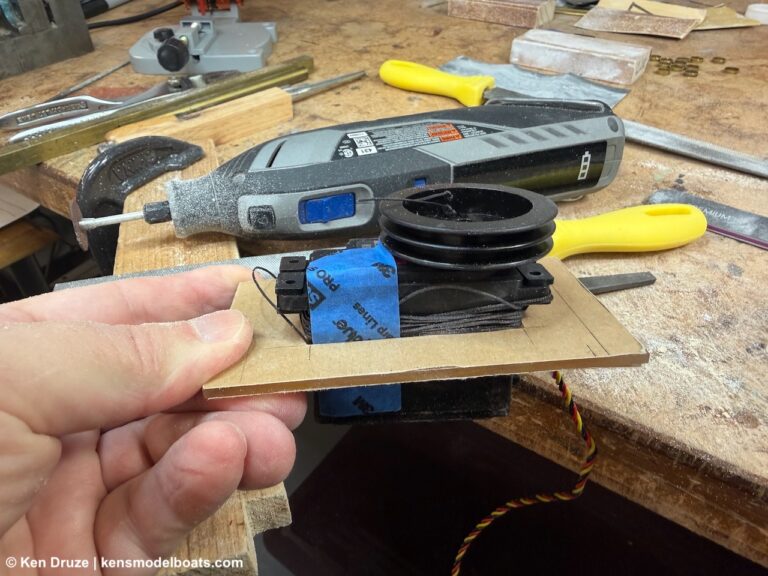
Gooseneck Insert
November 2026. The instructions call for taking a dowel and drilling a hole in it for the main boom pivot assembly. I do not like that suggestion. I do not use my lathe that often, so time to use it. I fashioned one insert for each mast. The Du-Bro linkage will be pressed fit into the insert with a vise. This gives it a more professional look.
Rudder Servo Mount, second attempt
December 2026. While I was determining how to setup the winch servo and pulley system, I saw that the rudder servo took up too much space that could be used for the winch servo. So, I made a second servo mount and used a smaller servo. This one is mounted to the boat with one machine screw on the front face of the epoxy rudder foundation. I had the Hitec servo on hand so I went with it as it was a smaller size. This servo mount is made so that if the servo needs to be replaced, three screws can be removed to take the servo out. If the replacement is not the same size then a new plate can be made to fit the new servo. I’m always thinking of how to make things easier for service. This gave me more room in front of the rudder servo.
Servo Winch Tray Part 1
December 2026. Being that I have not done this before, I researched online and looked at sailboats in person to get ideas. Then again I used my ingenuity to and skills to guess what needed to be done. I’m starting out making the winch tray using 3/8 x 1/2 basswood that I had on hand. The forward and aft crossmembers were made to fit in the position I wanted. Then the fore and aft sections were cut to length. Lap joints were cut with the mini table saw.
Servo Winch Tray Part 2
December 2026. I’ll be using Acrylic to mount the Servo Winch. Here the entire process is documented, see the picture captions for the description of each step. Not shown is making the slot. You can now see why I changed the rudder servo mount. I can either remove the servo spindle, or I can remove the entire servo mounted on the tray.
Layout of the area to be removed for the winch servo
Layout of the area to be removed for the winch servo
The perimeter was drilled to make it easier to use the Dremel
The Dremel with abrasive wheel was used to remove the center section
Center section removed
Begin cleanup with files
Cleanup progress using files
Trial fit
Completed cutout
Marking holes for machine screws
Holes drilled for machine screws and holes are tapped
Trial fit of mounting screws
Trial fit on the tray, in the boat
Trial fit in on the tray, in the boat, with the deck placed in position
Holes drill for a retaining screw
A t-nut was placed on the bottom
Trial fit on the tray, in the boat
Trial fit on the tray, in the boat, with the deck placed in position
The front of the winch mount slides into the slot, then the machine screw holds it in place
The front of the winch mount slides into the slot, then the machine screw holds it in place
Servo Winch Tray Part 3
December 2026. The forward part of the tray will extend under the deck past the mast and will not be accessible. Risers were added to bring the pulley up to the same height as the servo winch. The pulley is mounted on a removable acrylic tray should the winch line need attention. With the mast removed the pulley tray can be installed and removed by sliding it in the risers. The front and middle of the tray will be held in place by hold downs. The aft end has a bolt which will lock the pulley tray in place. As can be seen in the last few pictures, the forward pulley is beyond where the jib fairlead exits though the deck. The winch servo is aft of the main boom fairlead. Therefore, the available 14 inches of travel and exit points through the fairleads do not cross the pulley or winch servo, lessoning any chance of tangles. This sounds good to me for being a novice to sailboats. As Spock would say, that is logical (at least to me it is). The distance between the jib and main fairleads are 13 1/8 inches. The endpoints on the radio can be adjusted to change the winch line travel.
Location of the jib fairlead and mast in relation to the tray
This is the forward pulley mounted on a test piece of wood
An aluminum washer (on the bolt) and a spacer was turned on the mini-lathe
Marking wood, first mark was made, then turned, and the mark transferred to all four sides
Placing the pulley acrylic tray in position
Riser board for the pulley tray. The acrylic tray slides in and is held down by this part
All edges are rounded over to prevent the lines and sheets from snagging
Pulley tray in position with risers underneath
Pulley tray in position with risers underneath
Pulley tray in position with risers underneath
Transferring the fairlead position onto the pulley tray
With the pulley bolted to the tray you can see the filed out postion for the bolt head to slide through
So the tray does not flex, a support structure will be needed
This riser is modified for the supports
Supports added to the riser
Overall shot of the whole tray
Overall shot of the whole tray
The aft fairlead exit point in relation to the servo winch
Forward pulley area
Video Demonstration of Sail Winch and Rudder Servo
December 2026. This is a video demonstration of the sail servo winch mechanism and the rudder servo linkage.
Tthe two cross members you see above the winch lines are there to keep the line down and away from the underside of the deck once the deck is installed. Preventative so there are no possible tangles. I’ll explain this item later.
Servo Winch Tray Part 4
December 2026. Support needed to be added between the two risers to help slide the pulley tray into place. I went to the scrap pile for a small size strip of wood. Slots were cut in the two risers to support it. Once the whole tray is glued together they will be glued in place.
To insert the pulley tray, the line is wrapped around the pulley and the line will be tapped to the Acrylic sheet. Then it is placed on the support and slid into the first riser, then slid into the front riser, then the screw is secured. Then the line is attached to the spring/winch line. This of course is without the mast in place.
Support is needed between these two risers
Going to the scrap wood pile
Used the Dremel to make a ledge for the support to sit on
Slots were cut on the mini table saw on the right riser
Trial fit of the support and risers in place
Trial fit of the support and risers in place
Being that most of this is out of site, the Acrylic tray is placed on the support
Then it is slid into the first hold down rise
Then it slides into the extension that holds the end down
Here you can see how for under the deck this part of the tray will be
Winch Line Guides
January 2026. At this point I am not sure how the deck supporting structure will look. To keep the winch lines being pulled by the sheets, and maybe snagging on the underside of the deck, I added these guides to keep the winch lines from being pulled upwards. One side will be glued to the tray and the other side will have magnets to attach to the tray. The 1/4 inch dowel will be a slip fit in the holes. Should it need to be removed, the side with the magnet can be slipped off and the dowel removed from the fastened side. The holes were drilled undersize so the 1/8 by 3/16 inch magnets are a press fit into the holes and CA glue was added before the magnets were pressed into position .
Power Module
January 2026. The only electronic components needed are the receiver and a BEC, and of course a battery pack. A tray from acrylic was made to hold the receiver and BEC in place. Doubled sided tape secured them to the acrylic. On the underside of this part, Wago connectors from Amazon were used to connect positive and negative wires. The top part has a slide switch from an RC kit. A voltmeter was also mounted, again from Amazon. The top plate also had magnets pressed fit into the corners to hold the tray in place. The two peices were held together with four 080 machine screws. The volt meter is connected between the switch and the BEC. When power is applied, the voltmeter will indicate the actual battery voltage. In the second to last picture you can see the meter reading 5.47 volts. That is with a 4 cell AA pack. One or more of the batteries were low and the servo were getting lots of jitter. So I replaced the pack with a 6 cell pack which gave me 8.88 volts as can be seen in the last picture. This should eliminate any battery issues for the receiver. I might go with rechargeable NiMH batteries. Once I know what batteries I’ll be using, I will add a label by the meter indicating the optimal voltage.